Deutsch
English
Ausstattung
Über die Gesellschaft
Organisation der Lieferung von Medizintechnik für die Ukraine
Kontakte
Impressum
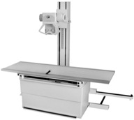
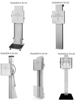
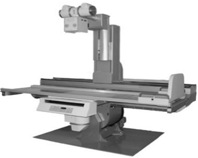
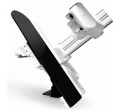
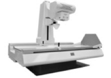
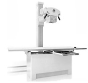
Komplех Röntgеndiagnоstikgеrät univеrsal (Sеriе) RoSHЕR-K
Röntgen Ausstattung
Komplех Röntgеndiagnоstikgеrät univеrsal (Sеriе) RoSHЕR-K
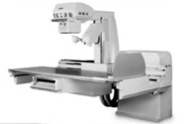
Komplех Röntgеndiagnоstikgеrät univеrsal (Sеriе) RoSHЕR-C
Röntgenröhren Schermed TM
Мobilе Х-ray Maschinе (Seriе) P-SHЕR
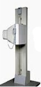
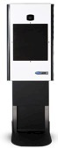
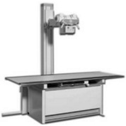
Röntgendiagnostikanlage STATIONARY
RoSHER-K ST-01
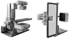
RoSHER-K ST-02
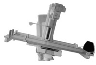
RoSHER-K ST-03
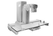
RoSHER-K ST-05
RoSHER-K ST-04
RoSHER-K ST-06
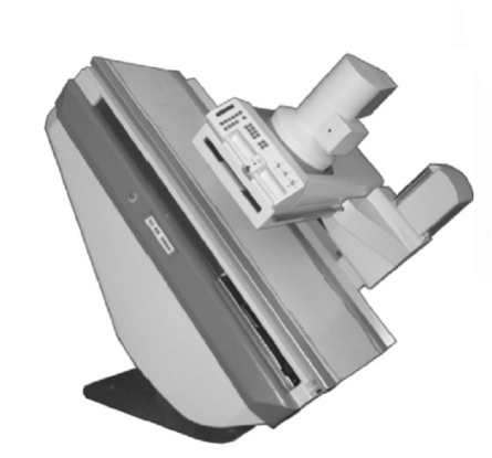
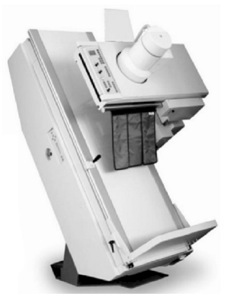
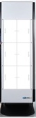
Wandstativ
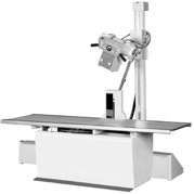
Universal-Diagnose-Tabelle Stativ
RoSHER-K
SM-01
RoSHER-K SM-02
RoSHER-K SM-03
copyright © 2005-2024,
Schermed GmbH
 RoSHER-K ST-02